SolidFace Parametric CAD Modeler 2D/3D
Release: 2014
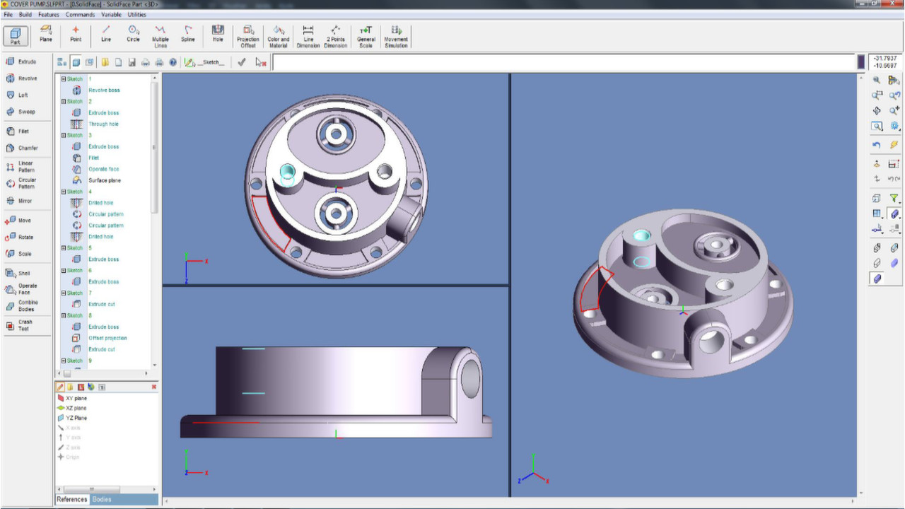
Part module
SolidFace Sketch automatically creates parametric reference for modeling features that can be edited in a very simple and interactive way. This is an in-house developed module and fully integrated with the 3D module.
SolidFace allows multiple bodies creation. A powerful tool helps in the development of dependent parts from a single part file.
The parameterization allows not only an easy model editing, but also parts family creation that is an important issue in automating creation of variant models with the same constructive basis, such as fasteners, automotive, hydraulic and civil components. From a parametric part you can automatically generate dozens of others parts through parameters association, such as thickness, length, number and diameter of holes, color, material, information, text, etc.
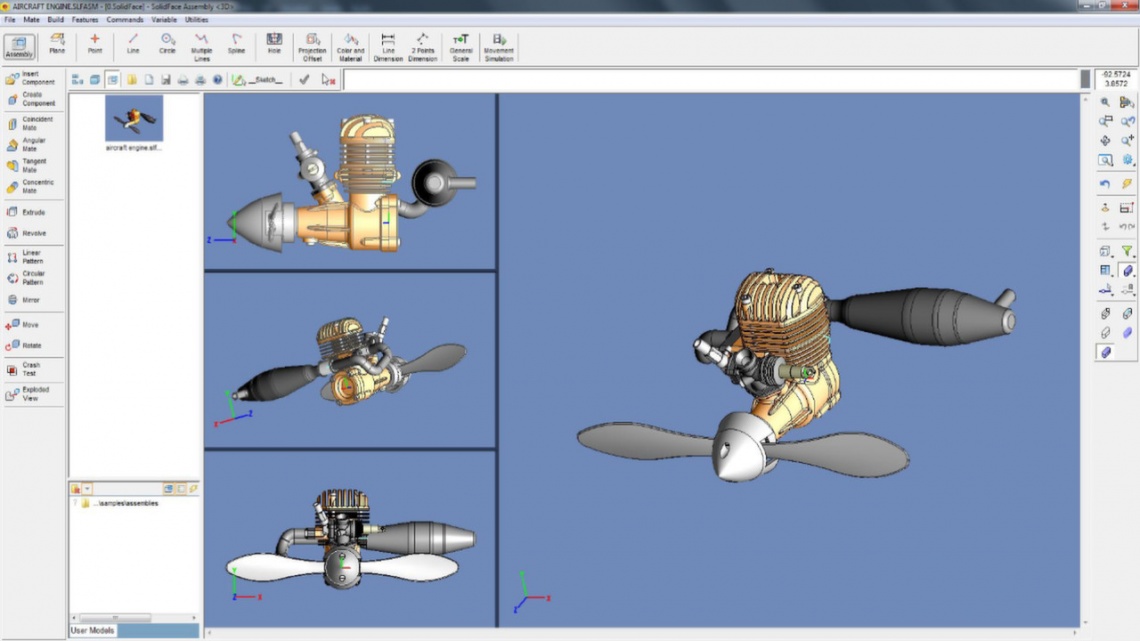
Assembly module
Easy, accurate and effective, this module enables you to build assemblies using modeled parts and sub-assemblies. The automatic link between the modules facilitates the manipulation of assembly parts, thus any editing on a part or assembly, results in an automatic change in the assembly that references this component.
You can build assemblies by inserting components created outside the assembly document; this is known as bottom-up assembling or if you need to construct a component that needs dimension references of some assembly components, you can create it, within the Assembly module. This operation is called in-context or top-down part creation.
To facilitate the assembly process, the part elements can be enabled or disabled at any time without interfering the process of inserting (bottom-up) or creating (top-down) new components.
Drawing module
Besides the 2D draft capabilities explained in the SolidFace drawing product, you can also insert parts and assemblies into the drawing module in order to generate automatic orthographic, sections and details views. These views and dimensional annotations are created according to DIN and ANSI norms. Personalized by the designer. The 3D models views can be displayed in several model styles. The sections or details views are automatically created and aligned with the base view.
Another advantage of the automatic link between the modules is the ability to copy and paste 2D geometric entities to the 3D Sketch module in order to use it as reference geometry to 3D features operations like extrude, revolve, etc.
Exploded view
An exploded view is a diagram, picture or technical drawing of an object, that shows the relationship or order of assembly of various parts. This allows the components (parts and sub-assemblies) to be visualized with defined displacements. The exploded view can be enabled or disabled at any time of the project creation.
3D Direct modeling
Interact directly with the geometry of the model. Manipulate it by pushing, pulling, or twisting.
Keeping the steps that create the final model, direct modelling allows the features geometry to be parametric modified by editing the feature used to create the new faces.
2D/3D Movement simulation
One of the many capabilities of logical conditions is to enable the system to detect the collision of components assembly. The collision or the simulation process can be aborted and analyzed at any time. This makes possible not just a simple mechanism video demonstration but also a real-time movement simulation.
The parameterization capability is one of the greatest advantages of SolidFace and it is present in all design steps. 3D Motion simulation is no different; the simulation is updated simultaneously with the movement. Another important capability is the simulation of 2D mechanisms, which can be performed either in 2D drawing or in 3D sketch module.
SolidFace Sketch automatically creates parametric reference for modeling features that can be edited in a very simple and interactive way. This is an in-house developed module and fully integrated with the 3D module.
SolidFace allows multiple bodies creation. A powerful tool helps in the development of dependent parts from a single part file.
The parameterization allows not only an easy model editing, but also parts family creation that is an important issue in automating creation of variant models with the same constructive basis, such as fasteners, automotive, hydraulic and civil components. From a parametric part you can automatically generate dozens of others parts through parameters association, such as thickness, length, number and diameter of holes, color, material, information, text, etc.
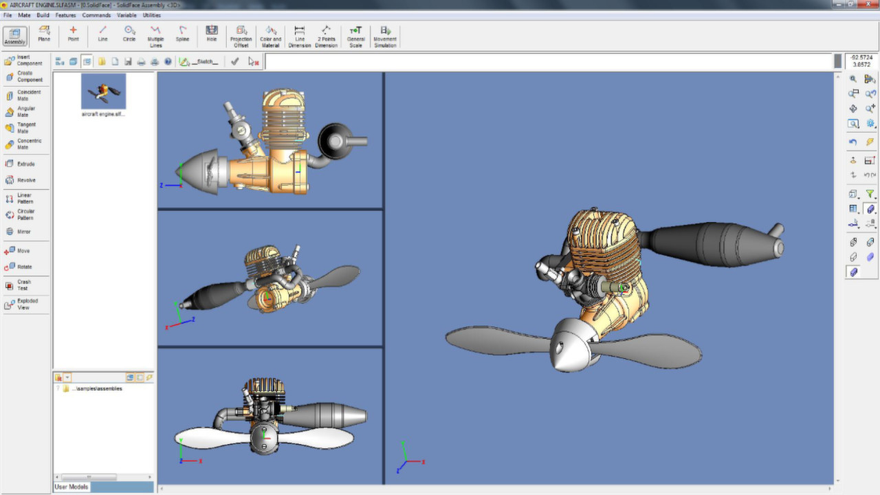
Assembly module
Easy, accurate and effective, this module enables you to build assemblies using modeled parts and sub-assemblies. The automatic link between the modules facilitates the manipulation of assembly parts, thus any editing on a part or assembly, results in an automatic change in the assembly that references this component.
You can build assemblies by inserting components created outside the assembly document; this is known as bottom-up assembling or if you need to construct a component that needs dimension references of some assembly components, you can create it, within the Assembly module. This operation is called in-context or top-down part creation.
To facilitate the assembly process, the part elements can be enabled or disabled at any time without interfering the process of inserting (bottom-up) or creating (top-down) new components.
Drawing module
Besides the 2D draft capabilities explained in the SolidFace drawing product, you can also insert parts and assemblies into the drawing module in order to generate automatic orthographic, sections and details views. These views and dimensional annotations are created according to DIN and ANSI norms. Personalized by the designer. The 3D models views can be displayed in several model styles. The sections or details views are automatically created and aligned with the base view.
Another advantage of the automatic link between the modules is the ability to copy and paste 2D geometric entities to the 3D Sketch module in order to use it as reference geometry to 3D features operations like extrude, revolve, etc.
Exploded view
An exploded view is a diagram, picture or technical drawing of an object, that shows the relationship or order of assembly of various parts. This allows the components (parts and sub-assemblies) to be visualized with defined displacements. The exploded view can be enabled or disabled at any time of the project creation.
3D Direct modeling
Interact directly with the geometry of the model. Manipulate it by pushing, pulling, or twisting.
Keeping the steps that create the final model, direct modelling allows the features geometry to be parametric modified by editing the feature used to create the new faces.
2D/3D Movement simulation
One of the many capabilities of logical conditions is to enable the system to detect the collision of components assembly. The collision or the simulation process can be aborted and analyzed at any time. This makes possible not just a simple mechanism video demonstration but also a real-time movement simulation.
The parameterization capability is one of the greatest advantages of SolidFace and it is present in all design steps. 3D Motion simulation is no different; the simulation is updated simultaneously with the movement. Another important capability is the simulation of 2D mechanisms, which can be performed either in 2D drawing or in 3D sketch module.
Get This Game

Images & Video
Recommended for You 